Free pharmacy material


Viscosity Determination
INTRODUCTION
Viscosity is defined as the resistance in the flow of liquid. It is also defined as the internal friction between two layers of liquid which resists the flow of liquid.
George Gabriel Stokes derived an expression in 1851 known as Stokes’ law.
Fd = −6ΠμRVs
where Fd = frictional force; μ = dynamic viscosity; R = radius of the spherical object; Vs = viscosity.
Then he defined the viscosity as the resistance in the flow of liquid at applied stress.
FACTORS AFFECTING VISCOSITY
- Size of molecules: High particle size solutions show high viscosity. That is, the size of the molecules is directly proportional to the viscosity.
- Shape of the molecules: Spherical molecules show low viscosity.
- Inter-molecular forces: Large inter-molecular forces have greater viscosity.
- Temperature: Temperature is directly proportional to the viscosity.
TYPES OF VISCOMETERS
There are mainly four types of viscometers mainly employed for the determination of viscosity:
Capillary Viscometer
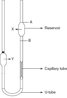
This is mainly based on the principle of the measurement of the time taken for the liquid to flow between the marks. This is commonly known as Ostwald viscometers.
The Ostwald viscometers consist of a U-tube with two bulbs (one is for sample). A capillary tube is fixed above the U-tube. The liquid sample is filled in the bulb X, and the time is noted for the flow of the sample from Mark A to Mark B. This is then repeated for a known liquid such as water. Then the viscosity of the sample is expressed by the following formula:
where η1 = viscosity of the sample solution; η2 = viscosity of the water; p1 = density of the sample; p2 = density of the water; t1 = time taken to flow from Mark A to Mark B of the sample in seconds; t2 = time taken to flow from Mark A to Mark B of the water in seconds.
This equation is mainly based on Poiseuille's law for a liquid flowing through a capillary tube.
η = Πr4tΔp/8lv
where r = radius of the capillary; t = time of flow; Δp = pressure difference; l = length of the capillary; v= volume of the liquid flowing through the capillary.
Capillary viscometer
Falling Sphere Viscometer
In this method, the metal or glass ball rolls down in a vertical glass tube which is filled with the sample solution. The sample tube is filled with the sample solution. The ball is then immersed in the sample solution. The temperature of the sample tube is maintained with the water jacket surrounding the sample tube. Then, after attaining the temperature equilibrium, the whole system is inverted, that is, the ball is placed at the top of the solution, and the time taken for the ball from Mark A to Mark B is noted. The procedure is repeated several times for accurate results. Then the viscosity of the sample liquid is calculated from the following equation:
Falling sphere viscometer
η = t (Sb − Sf) B
where t = time taken for the ball to fall from Mark A to Mark B; Sb = specific gravity of the ball; Sf = specific gravity of the sample; B = constant for the ball.
Cup-Bob Viscometer
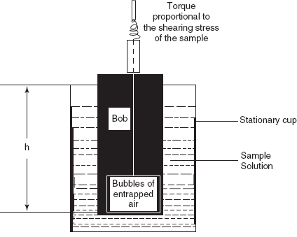
This method is also known as the Couette viscometer which is based on shear rates. The sample is sheared in the space between the outer wall of the bob and the inner wall of the cup into which the bob is fitted. Then the viscosity is determined by the following formula:
η = KvT/Ω
where Kv = constant; T = torque; Ω = angular velocity.
Cup-Bob viscometer
The angular velocity is given by the following formula:
Ω = (1/η) (T/4Πh) (1/Rb2 − 1/Rc2)
where T = torque; h = the depth of the bob immersed in the liquid; Rb and Rc are the radii of the bob and cup, respectively.
The main disadvantage of the cup and bob viscometer is variable shear across the sample between the bob and the cup.
Cone and Plate Viscometer
The cone is driven by variable speed motor and the sample solution is sheared in the narrow gap between the stationary plate and the rotating cone. The sample solution is placed at the centre of the plate.
Cone and plate viscometer
The viscosity is given by the following formula:
η = CXT/v
where C = constant; T = torque reading; v = speed of the cone.
UNITS FOR THE VISCOSITY
The SI units of the viscosity are the Pascal second or in cgs units poise or centi poise.
APPLICATIONS
- Used in the determination of intrinsic viscosity
- Used in the determination of light fuels
- Used in the control of polymerization
- Used in the determination of the flow of different solvents through the pumps used in HPLC or GC
- Used in the determination or study of the physical properties of liquids
REVIEW QUESTIONS
- Define viscosity.
- Explain Stokes’ law.
- What are the factors affecting viscosity?
- Explain the principle involved in the cup and bob viscometer.
- Explain the principle involved in the capillary viscometer.
- Explain the principle involved in the falling sphere viscometer.
- Explain the principle involved in the cone and plate viscometer.
- What are the applications of viscometer determinations?
Comments